|
|
|
|
If you can improve on the narrative that accompanies
the following photos then please email me.
|
|
|
|
|
|
 |
|
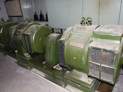
008 - A 'Continuity Set'. A DC motor is powered by the
exchange batteries and drives an AC generator which maintains an
uninterrupted mains voltage supply to transmission equipment
during a failure of the grid. Meanwhile the engines start up and
take over. If there are problems starting the main engines then
this will give some leeway while they are sorted out. |
|
|
|
|
|
|
|
 |
|
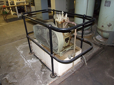
004 - A small electrically driven compressor which supplied air
to the tanks in the top right corner. This compressed air would
have been used as a means to start the diesel engines. |
|
|
|
|
|
|
|
 |
|
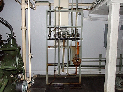
005 - Fuel control valves. The station had enough fuel to last for
four weeks. |
|
|
|
|
|
|
|
|
|
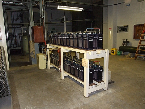
003 - Batteries to supply an uninterruptable power supply (UPS) to
essential equipment and lighting in the event of power failure.
This photo shows a much reduced battery supplying what was left
working in the station. Originally there were battery rooms with
very large open lead acid cells for standby operation. |
|
|
|
|
|
|
|
|
|
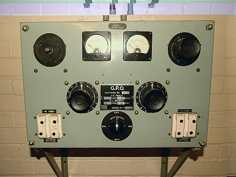
012 - A mercury lamp rectifier used to produce a clean DC current
from an AC input. The sides of the cabinet would have had grills
fitted in them and an bright white light would be seen when the
device was running. It was used to charge the batteries. |
|
|
|
|
|
|
|
 |
|
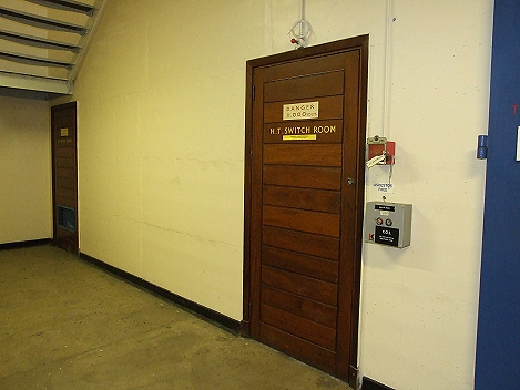
042 - Door leading the the high voltage (HV) switch room. The sigh
warns of 11,000 volts (11kV). |
|
|
|
|
|
|
|
 |
|
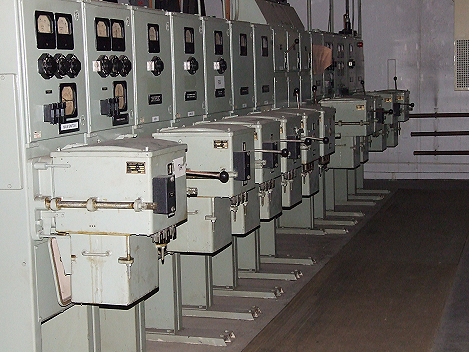
006 - High voltage switchgear. |
|
|
|
|
|
|
|
|
|
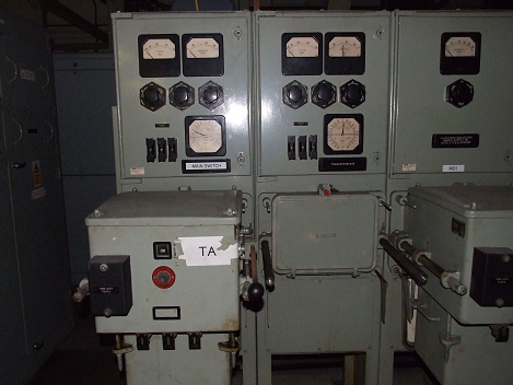
034 - A closer view of the switchgear. |
|
|
|
|
|
|
|
click
the arrow |
|
< |
page
4 of
7 |
> |
|
|
|

|